ATEN SXP-500 User Manual
Browse online or download User Manual for Video converters ATEN SXP-500. ATEN SXP-500 User manual
- Page / 12
- Table of contents
- TROUBLESHOOTING
- BOOKMARKS
Summary of Contents
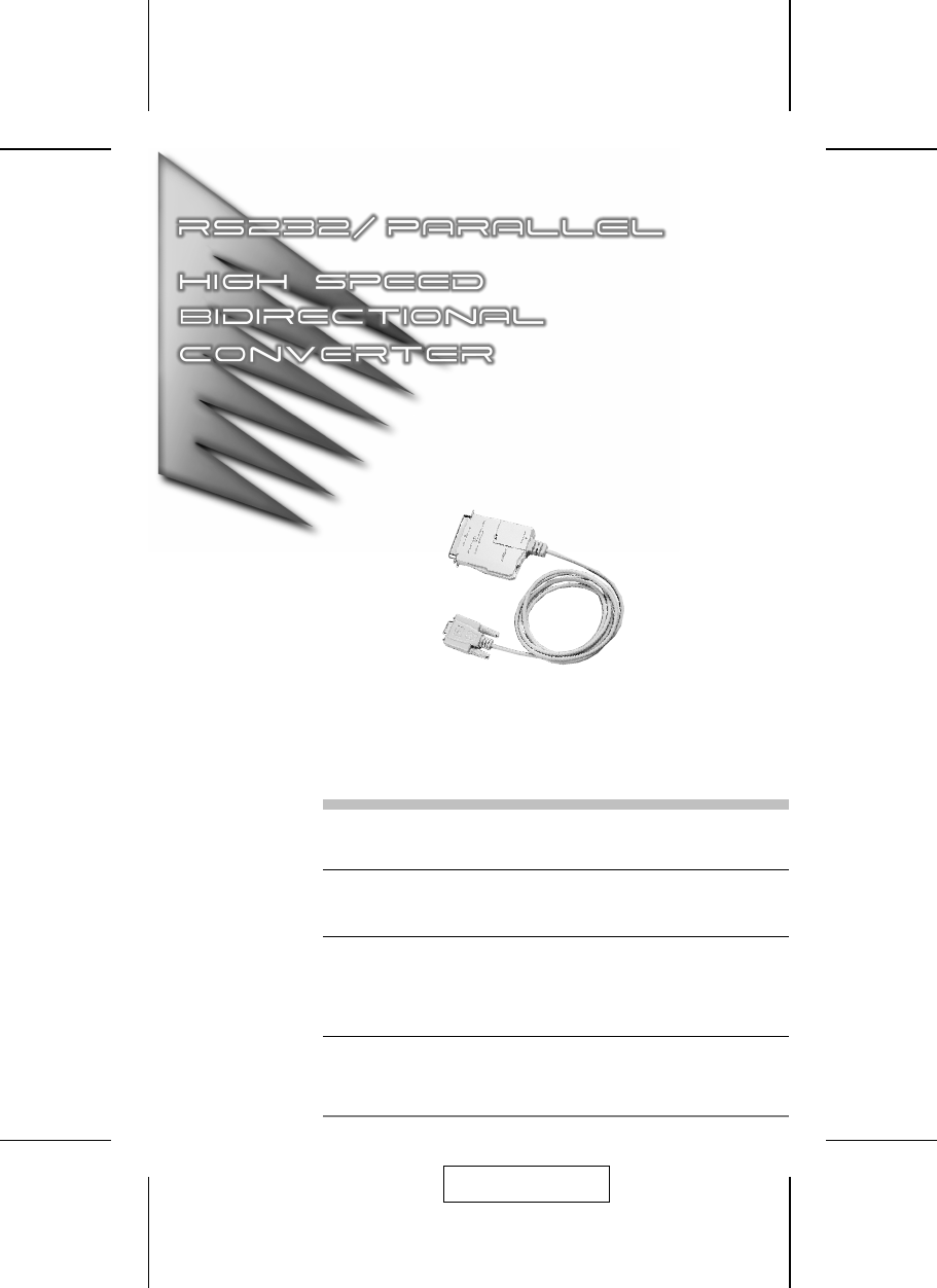
User ManualSXP-500Read this guide thoroughly and follow the installation and operationprocedures carefully in order to prevent any damage to the units
Centronics Interface SpecificationPin Name Function1STB DATA STROBE2DATA BIT 1 DATA BUS3DATA BIT 24DATA BIT 35DATA BIT 46DATA BIT 57DATA BIT 68DATA BI
TroubleshootingSymptom Possible Cause ActionPower LED doesnot lightCables are not properlyplugged in.Make sure that all cables are properlyplugged in
Radio & TV Interference StatementWARNING!!! This equipment generates, uses and can radiate radiofrequency energy and, if not installed and used in
OverviewThe SXP-500 is an interface converter that allows Centronics and RS-232devices to communicate with each other (a computer with an RS-232outpu
Rear ViewDIP Switch ConfigurationOverview:The SXP-500 is configured by setting an eight segment DIP Switch asfollows:Switch Purpose123Baud rate Settin
DIP Switch SettingsBaud Rate:The baud rate is set with DIP Switch segments 1 - 3 (located on the bottompanel), and JP1 (located inside the housing), a
CablingSerial to Parallel:When performing a Serial to Parallel interface conversion:1. Plug the attached serial cable (with DB 9 female connector) lea
Parallel to Serial:When performing a Parallel to Serial interface conversion:1. Use an IEEE1284 Parallel cable with a male D25 connector at oneend, an
Serial Port Cabling:Parallel Port Cabling:- 6 -SXP-500DCEDB-9 3 2 7 8 6 4 5Device Connector’s Pin #DCE DTE DCE DTEDB-9 DB-9 DB-25 DB-25 2 3
OperationWhen operating the SXP-500, please take note of the following:1. Since the SXP-500 is a DCE device, the serial device it connects tomust be c
RS-232C Interface SpecificationThe RS-232C Interface DCE mode (default) specification is given in thetable below:Pin Name Function1 CD PULL Up (+9v)2
Related products and manuals for Video converters ATEN SXP-500
 (32 pages)
© 2020, manymanuals.com. All rights reserved. | 0.040 s |
 Manymanuals.com
 Manymanuals.de
 Manymanuals.fr
 Manymanuals.it
 Manymanuals.pl
 Manymanuals.cz
 Manymanuals.es
 Manymanuals-pt.com
Comments to this Manuals